RL03 TX Assembly and Wiring
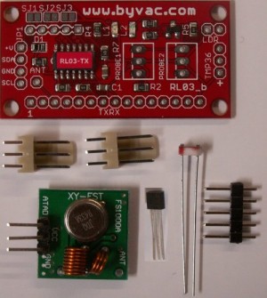
Parts List
- PCB Board with SMD Components
- 3 way polarised pins x 2
- LDR
- 4 way pinhead
- DS18B20 temperature sensor
- Transmitter
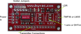
The TX board comes in kit form and the polarized plugs and LDR are marked on the board so there should be no difficulty in assembling that part. The 4 way pinhead is for the power supply that can be taken from JP1. Note that the board is also used for a receiver and so I2C markings are on that connector but for this use the SDA and SCL pins are not used.
The kit is supplies with a single DS18B20, if this is to be used there is no need to fit the polarised connectors as the DS18B20 can be directly soldered to the probe pads, either probe-1 or probe-2.
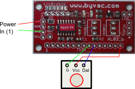
Connections the supplied transmitter. The antenna is on the Transmitter board. In practice this works well with a good quality receiver.
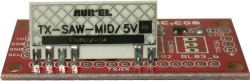
Connections for the top quality AUREL transmitter. If this is used then SJ3 requires closing as it supplies power to pin 1.
Power
The TX board will work from 3V* to 6.5V and so a 4 x 1.5V battery pack or 2 x CR2330 cells or various combinations can be used. The processor maximum voltage is about 5.5V and so a diode is provided that drops this voltage when using 6V or more. If the board is being powered by less then 6V then SJ1 should be closed, this will remove the effect of the diode.
* The transmitter supplied needs 5V to operate
| Powered By | SJ1 |
| 4 x 1.5 volt alkaline batteries (6V) | Open |
| 3 x 1.5 volt alkaline batteries (4.5) | Closed |
| 4 x 1.2 volt NiCad batteries (4.8V) | Closed |
| 3 x Lithium button cells (7V) | Open |
The table assumes that a 5V transmitter is connected any lower voltage and SJ1 should be closed.
Various transmitters can be used and provided there is a good receiver the transmitter type has only a small effect on the range and reliability. The main connection is the 15 way pads at the bottom of the PCB.
- Connected to SJ3 (SJ3 connected to +V)
- G1
- Antenna
- G1
- n/c
- n/c
- G1
- n/c
- G1
- TX data
- n/c
- n/c
- n/c
- n/c
- +V
G/G1 is ground but this is only switched on by the firmware when required. It should be connected to the TX ground.
Sensors
For using these see the Adding Sensors section
Not all sensors can be added at once. There is a table of what sensors can be automatically be detected. See the sensor Options table for details. The sensors are normally switched off until needed to save power.