RL03 TX_SW + TX_PIR Assembly & Wiring
There is no physical difference between the TX_SW board and the TX_PIR board only the firmware is different and so the instructions here apply to both.
|
Parts List TX_SW
|
Parts List TX_PIR
|
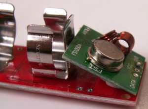
1) Install the battery holders.
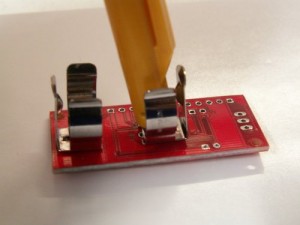
These are mounted at the back of the PCB and require a VERY firm push to get them as level as possible with the back of the PCB. Solder from the other side.
2) Transmitter (option 1)
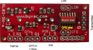
Straighten the transmitter pins and mount at the top of the PCB. The pins should correspond 1:1 with the PCB markings (G + D) where D is DATA and G is Ground, before soldering make sure that is the case.
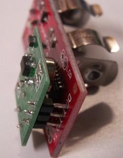
2) Transmitter (option 2)
If space is tight the transmitter can be mounted on the underside. For this remove the pins and mount the other way round so that the PCB pads still correspond with the transmitter pads.
This will save some space. The TX does need to be at a slight angle.
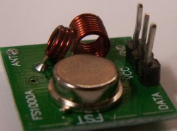
3) Antenna
This is a piece of wire 168 to 173mm long. Any wire will do for good results. It can also be coiled for enclosures with tight space. Some tips are given here about antennas. Check the loaded antenna in the pdf file for really good results although for general use it has been found that any old wire of correct length gives good results.
4) Install the sensors
There will always be an LDR, this can go anyway round and the pads are marked on the PCB. The sensor options and wiring are given on this page (Adding Sensors).
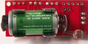
5) Battery
The battery is installed positive to the transmitter.